8.2. Communicating with the DUT
There are two types of DUTs that can be made: tethered or standalone DUTs. A tethered DUT is where a host computer (or just host) must send transactions to the DUT to bringup a program. This differs from a standalone DUT that can bringup itself (has its own bootrom, loads programs itself, etc). An example of a tethered DUT is a Chipyard simulation where the host loads the test program into the DUTs memory and signals to the DUT that the program is ready to run. An example of a standalone DUT is a Chipyard simulation where a program can be loaded from an SDCard by default. In this section, we mainly describe how to communicate to tethered DUTs.
There are two ways the host (otherwise known as the outside world) can communicate with a tethered Chipyard DUT:
- Using the Tethered Serial Interface (TSI) or the Debug Module Interface (DMI) with the Front-End Server (FESVR) to communicate with the DUT
- Using the JTAG interface with OpenOCD and GDB to communicate with the DUT
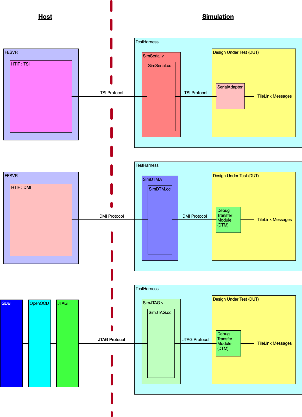
The following picture shows a block diagram view of all the supported communication mechanisms split between the host and the simulation.
8.2.1. Using the Tethered Serial Interface (TSI) or the Debug Module Interface (DMI)
If you are using TSI or DMI to communicate with the DUT, you are using the Front-End Server (FESVR) to facilitate communication between the host and the DUT.
8.2.1.1. Primer on the Front-End Server (FESVR)
FESVR is a C++ library that manages communication between a host machine and a RISC-V DUT. For debugging, it provides a simple API to reset, send messages, and load/run programs on a DUT. It also emulates peripheral devices. It can be incorporated with simulators (VCS, Verilator, FireSim), or used in a bringup sequence for a taped out chip.
Specifically, FESVR uses the Host Target Interface (HTIF), a communication protocol, to speak with the DUT. HTIF is a non-standard Berkeley protocol that uses a FIFO non-blocking interface to communicate with the DUT. It defines a protocol where you can read/write memory, load/start/stop the program, and more. Both TSI and DMI implement this HTIF protocol differently in order to communicate with the DUT.
8.2.1.2. Using the Tethered Serial Interface (TSI)
By default, Chipyard uses the Tethered Serial Interface (TSI) to communicate with the DUT.
TSI protocol is an implementation of HTIF that is used to send commands to the
RISC-V DUT. These TSI commands are simple R/W commands
that are able to probe the DUT’s memory space. During simulation, the host sends TSI commands to a
simulation stub called SimSerial (C++ class) that resides in a SimSerial Verilog module
(both are located in the generators/testchipip project). This SimSerial Verilog module then
sends the TSI command recieved by the simulation stub into the DUT which then converts the TSI
command into a TileLink request. This conversion is done by the SerialAdapter module
(located in the generators/testchipip project). In simulation, FESVR
resets the DUT, writes into memory the test program, and indicates to the DUT to start the program
through an interrupt (see Chipyard Boot Process). Using TSI is currently the fastest
mechanism to communicate with the DUT in simulation.
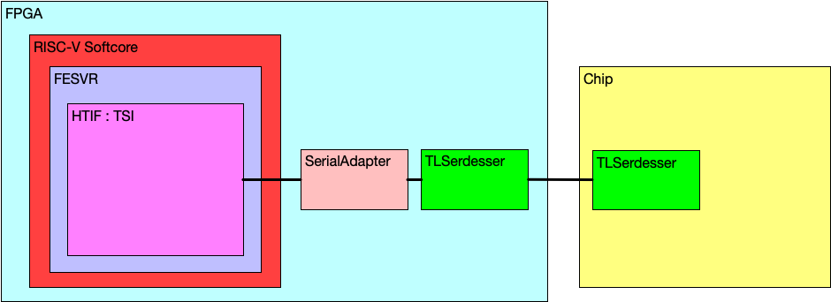
In the case of a chip tapeout bringup, TSI commands can be sent over a custom communication
medium to communicate with the chip. For example, some Berkeley tapeouts have a FPGA
with a RISC-V soft-core that runs FESVR. The FESVR on the soft-core sends TSI commands
to a TSI-to-TileLink converter living on the FPGA (i.e. SerialAdapter). After the transaction is
converted to TileLink, the TLSerdesser (located in generators/testchipip) serializes the
transaction and sends it to the chip (this TLSerdesser is sometimes also referred to as a
serial-link or serdes). Once the serialized transaction is received on the
chip, it is deserialized and masters a bus on the chip. The following image shows this flow:
Note
The TLSerdesser can also be used as a slave (client), so it can sink memory requests from the chip
and connect to off-chip backing memory. Or in other words, TLSerdesser creates a bi-directional TileLink
interface.
8.2.1.3. Using the Debug Module Interface (DMI)
Another option to interface with the DUT is to use the Debug Module Interface (DMI).
Similar to TSI, the DMI protocol is an implementation of HTIF.
In order to communicate with the DUT with the DMI protocol, the DUT needs to contain a Debug Transfer Module (DTM).
The DTM is given in the RISC-V Debug Specification
and is responsible for managing communication between the DUT and whatever lives on the other side of the DMI (in this case FESVR).
This is implemented in the Rocket Chip Subsystem by having the HasPeripheryDebug and HasPeripheryDebugModuleImp traits.
During simulation, the host sends DMI commands to a
simulation stub called SimDTM (C++ class) that resides in a SimDTM Verilog module
(both are located in the generators/rocket-chip project). This SimDTM Verilog module then
sends the DMI command recieved by the simulation stub into the DUT which then converts the DMI
command into a TileLink request. This conversion is done by the DTM named DebugModule in the generators/rocket-chip project.
When the DTM receives the program to load, it starts to write the binary byte-wise into memory.
This is considerably slower than the TSI protocol communication pipeline (i.e. SimSerial/SerialAdapter/TileLink)
which directly writes the program binary to memory.
Thus, Chipyard removes the DTM by default in favor of the TSI protocol for DUT communication.
8.2.1.4. Starting the TSI or DMI Simulation
All default Chipyard configurations use TSI to communicate between the simulation and the simulated SoC/DUT. Hence, when running a software RTL simulation, as is indicated in the Software RTL Simulation section, you are in-fact using TSI to communicate with the DUT. As a reminder, to run a software RTL simulation, run:
cd sims/verilator
# or
cd sims/vcs

make CONFIG=LargeBoomConfig run-asm-tests
FireSim FPGA-accelerated simulations use TSI by default as well.
If you would like to build and simulate a Chipyard configuration with a DTM configured for DMI communication, then you must tie-off the TSI interface, and instantiate the SimDTM. Note that we use WithTiedOffSerial ++ WithSimDebug instead of WithTiedOffDebug ++ WithSimSerial.
class dmiRocketConfig extends Config(
  new chipyard.iobinders.WithUARTAdapter ++
  new chipyard.iobinders.WithTieOffInterrupts ++
  new chipyard.iobinders.WithBlackBoxSimMem ++
  new chipyard.iobinders.WithTiedOffSerial ++
  new chipyard.iobinders.WithSimDebug ++               // add SimDebug and use it to drive simulation
  new chipyard.config.WithBootROM ++
  new chipyard.config.WithUART ++
  new chipyard.config.WithL2TLBs(1024) ++
  new freechips.rocketchip.subsystem.WithNoMMIOPort ++
  new freechips.rocketchip.subsystem.WithNoSlavePort ++
  new freechips.rocketchip.subsystem.WithInclusiveCache ++
  new freechips.rocketchip.subsystem.WithNExtTopInterrupts(0) ++
  new freechips.rocketchip.subsystem.WithNBigCores(1) ++
  new freechips.rocketchip.subsystem.WithCoherentBusTopology ++
  new freechips.rocketchip.system.BaseConfig)
Then you can run simulations with the new DMI-enabled top-level and test-harness.
cd sims/verilator
# or
cd sims/vcs

make CONFIG=dmiRocketConfig run-asm-tests
8.2.2. Using the JTAG Interface
The main way to use JTAG with a Rocket Chip based system is to instantiate the Debug Transfer Module (DTM) and configure it to use a JTAG interface (by default the DTM is setup to use the DMI interface mentioned above).
8.2.2.1. Creating a DTM+JTAG Config
First, a DTM config must be created for the system that you want to create.
This step is similar to the DMI simulation section within the Starting the TSI or DMI Simulation section.
The configuration is very similar to a DMI-based configuration. The main difference
is the addition of the WithJtagDTM config fragment that configures the instantiated DTM to use the JTAG protocol as the
bringup method.
class jtagRocketConfig extends Config(
  new chipyard.iobinders.WithUARTAdapter ++
  new chipyard.iobinders.WithTieOffInterrupts ++
  new chipyard.iobinders.WithBlackBoxSimMem ++
  new chipyard.iobinders.WithSimDebug ++    // add SimJtag and SimSerial, use both to drive sim
  new chipyard.iobinders.WithSimSerial ++
  new testchipip.WithTSI ++
  new chipyard.config.WithBootROM ++
  new chipyard.config.WithUART ++
  new chipyard.config.WithL2TLBs(1024) ++
  new freechips.rocketchip.subsystem.WithJtagDTM ++        // sets DTM communication interface to JTAG
  new freechips.rocketchip.subsystem.WithNoMMIOPort ++
  new freechips.rocketchip.subsystem.WithNoSlavePort ++
  new freechips.rocketchip.subsystem.WithInclusiveCache ++
  new freechips.rocketchip.subsystem.WithNExtTopInterrupts(0) ++
  new freechips.rocketchip.subsystem.WithNBigCores(1) ++
  new freechips.rocketchip.subsystem.WithCoherentBusTopology ++
  new freechips.rocketchip.system.BaseConfig)
8.2.2.2. Building a DTM+JTAG Simulator
After creating the config, call the make command like the following to build a simulator for your RTL:
cd sims/verilator
# or
cd sims/vcs

make CONFIG=jtagRocketConfig
In this example, the simulation will use the config that you previously specified, as well as set the other parameters that are needed to satisfy the build system. After that point, you should have a JTAG enabled simulator that you can attach to using OpenOCD and GDB!
8.2.2.3. Debugging with JTAG
Please refer to the following resources on how to debug with JTAG.